
Q.1. Discuss LCR circuit with phaser diagram.
Ans ⇒ LCR circuit with phaser diagram : In this circuit inductance of coil (L), capacitance (C) and electric resistance (R) are connected in series. If strength of current in circuit is I then p.d. across R is VR. Which is in phase of current. But in inductor, induced p.d. is ahead of current by phase π/2 In case of capacitor p.d. Vc across C is lagging behind in phase by π/2 with current. So phase difference between VL & Vc is 180°.
. Then its value is VL – VC. The phase difference with VR is π/2.
Now p.d. in L-C-R Curcuit is V2 = V2R +(VL – VC)2.
Since VR = IR, VL = IXL, VC = IXC
Here, XL → inductive reactance & XC → capacitive reactance. So, V2 = I2R2 + (IXL – IXC)2
. ![]() . .
. . 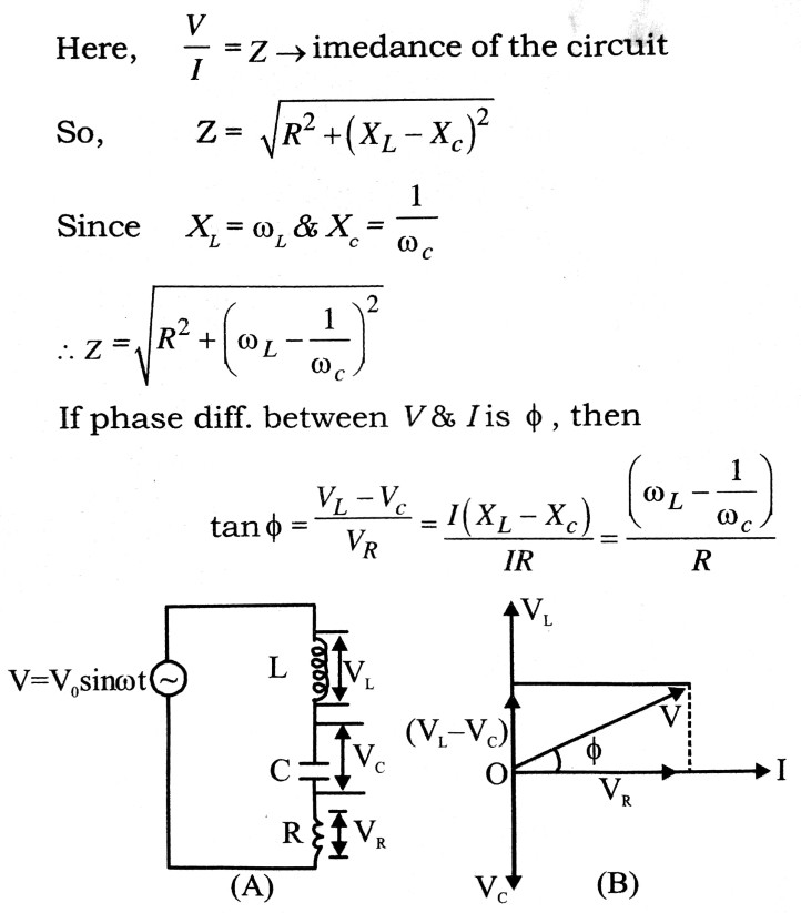
So, here it is clear that the value of φ depends upon relative value of R, XL & XC
. In case of resonance → XL = XC and tan φ = O i.e., V & I will be in same phase. In this situation Z = R. In this condition value of current is the maximum. this is called electrical resonance.
Resonant frequency,![]()
Q.2. Find an expression for average, mean and r.m.s. value of a.c.
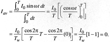
Ans ⇒ Average value of a.c. : The average value of a.c. for complete cycle
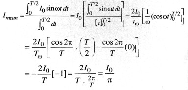
Mean value of a.c. : The mean value of a.c. for positive or negative half cycle is
 R.M.S vallue of a.c. I = I0 sin ωt
. 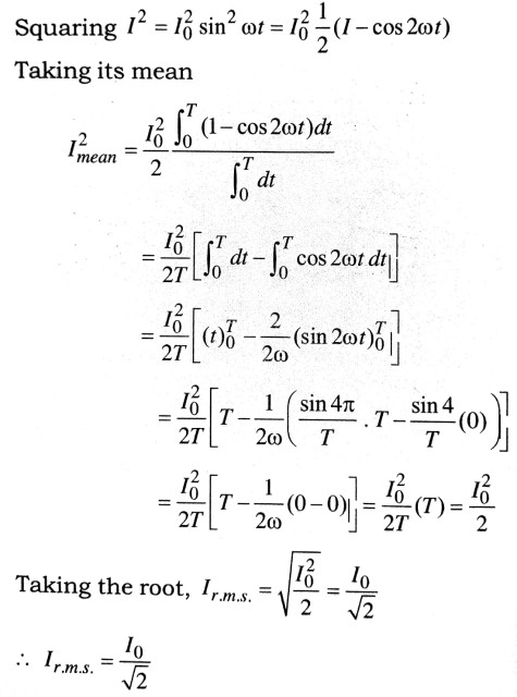
Peak value of current, I0 = 1r.m.s. = √2
∴ Ir.m.s. is also called virtual value of current.
Q.3. What are step up and step down trans formers ? Give the theory of a transformer and discuss its working. Describe the various losses occuring in a transformer. How are they reduced ?
Ans ⇒ A transformer, based on the principle of mutual induction, is a device which is used to change the voltage of alternating current as large alternating current at low voltage into small current as high volt age and vice-versa. As such transformers are of two types.
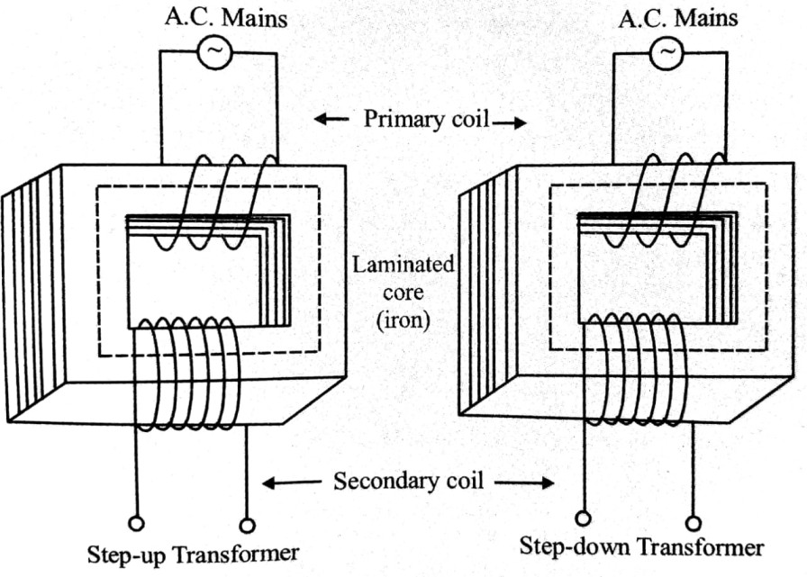
(i) Step up transformer : The transformer which convert low voltages into higher ones are called the step-up transformer.
(ii) Step down transformer : The transformer which convert high voltages into lower ones are called step down transformers.
Transformers are used only in a. c., not in d.c.
Construction : A transformer consists of two coils, called the primary and secondary, which are insulated from each other and wound on a common soft-iron laminated core as shown in figure. The alternating voltage to be transformed is connected to the primary while the load is connected to the secondary. In step up transformer the primary coil consists of a few turns of thick insulated copper wire and the secondary consists of a large number of turns of thin insulated copper wire, while reverse the case in a stepdown transformer.
Theory : When an alternating voltage is applied to the primary, an alternating current flows in the coil. This sets up an alternating magnetic flux in the core. This magnetic flux is linked up with both the primary and the secondary. Hence an induced alternating e.m.f. is produced in the primary as, well as in the secondary.
Let NP and NS be the number of Turns in the primary and the secondary coils respectively. Let as sume that there is no leakage of magnetic flux so that the same flux passes through each turn of the primary and the secondary. Let ΦB be the flux linked with each turn of cither coil at any instant. Then, by Faraday’s law of electromagnetic induction the e.m.f. induced in the primary is given by and the e.m.f. induced in the secondary,
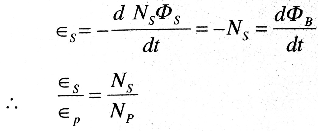
If the resistance of the primary circuit be negligible and there be no energy losses, the induced e.m.f. εp in the primary will be numerically equal to the applied voltage εp across the primary. Further, if the secondary circuit be open the voltage εs across the terminals of the secondary will be equal to the induced e.m.f. εs, under these ideal conditions.
. ![]() … (i)
… (i)
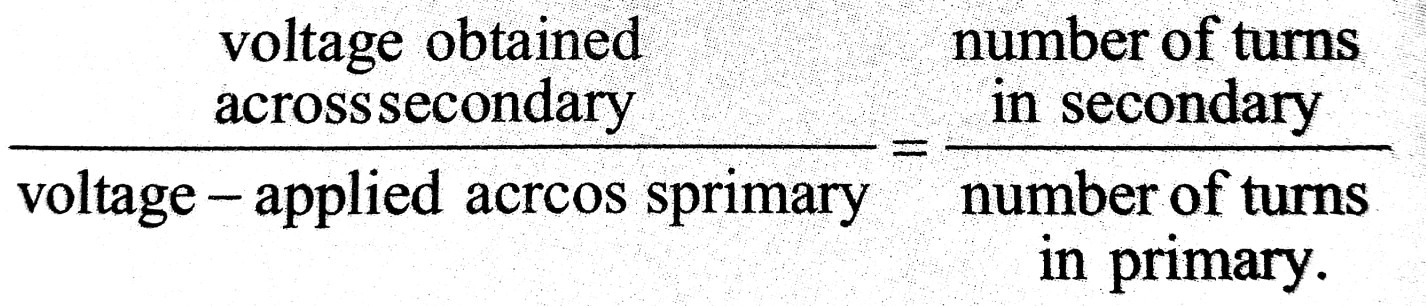
where k is called the transformer ratio. Thus,
. 
Let ip and is be the currents in the primary and the secondary at any instant and the power losses be zero. then
Power in the secondry = Power in the primary
i.e. ES x is = Ep x ip
![]() …(i)
…(i)
Thus, when the voltage is stepped up, the current is correspondingly reduced in the same ratio, and vice-versa.
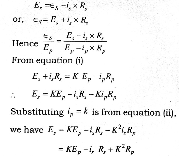
However, if the primary circuit has an appre ciable resistance KP, the difference between the applied voltage Ep and the back e.m.f. εp must be equal to the potential drop ip x Rp, in the primary coil i.e.
Ep – εp = ip x RP
εp = EP – eP x RP
Again, if the secondary circuit is closed having finite resistance (load) Rs, a part of the induced e.m.f. εs in the secondary overcomes the potential drop is x Rs, so that the available potential difference across the secondary is given by
. 
In this case ![]() is not a constant but decreases with increase in load or drawing more current in the secondary circuit.
is not a constant but decreases with increase in load or drawing more current in the secondary circuit.
Energy losses in a transformer: The power out put of a transformer is neccessarily less than the power input because of unavoidable energy losses. These losses are :
(a) Copper losses : As the alternating current flows through the primary and secondary, heat is developed in side the copper turns. This waste of en ergy is known as copper losses.
(b) Eddy current losses : Eddy currents are set up in the iron core of the tranformer, and these gen erate heat, with consequent loss of energy. To minimise these losses the iron ore is laminated by making it of a number of thin sheets of iron insu lated from each other, instead of making it from one solid piece of iron.
(c) Hysteresis losses : During each cycle of A.C. the core is taken through a complete cycle of magnetisation. The energy expanded in this process in finally converted into heat and is therefore wasted. This loss is minimised by using the core of a mag netic alloy for which the area of the hysteresis loop is a minimum.
(d) Losses due to leakage of flux : All the flux linked with the primary are not linked with the sec ondary.
Q.4. Explain the terms or derive expression for Power and power factor in an A.C. Circuit. Describe experimental measurement of power factor.
Ans ⇒ Power and Power Factor in an A.C. Circuit : The power in an electrical circuit is the rate at which electrical energy is consumed in the circuit, and is equal to the product of the voltage and the current. In an A.C. circuit the instantaneous value of the voltage and current are given by E = E0 sinωt and i = i0 sin(ωt – φ) where φ is the phase difference between current and voltage.
Hence the power in an A.C. Circuit at any instant
. 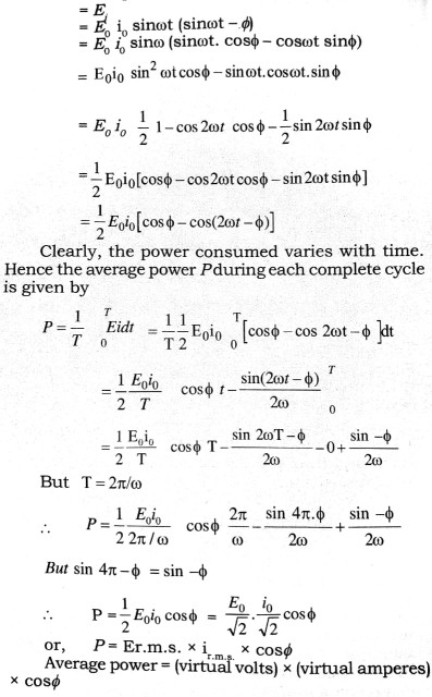
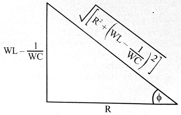
As cosø is the factor by which the product of the r.m.s. values of the voltage and current must be multiplied to give the power dissipated, it is known the power factor of the circuit. The value of coca depends on the nature of the circuit. For a circut containing pure resistarice, φ = 0), so that cosφ = 1. Por a circuit containing resistance, capacitance and in series, we have
. 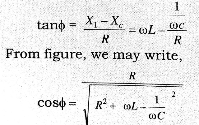
This is the expression for the power factor.
The current in A.C. circuit is said to be wattless when the average power consumed in the circuit is zero. This is possible when the power factor is zero i.e, when cosø = 0
or, φ = π/2 i.e. when the current and voltage differ in phase by π/2. For example, in a pure inductance the current lags behind the voltage by π/2. Hence the average power absorbed in a pure inductance and in a pure capacitance is zero.
Experimental Measurement of Power Factor : The experimental arrangement and the circuit diagram of measurement of power factor of given load is as shown in figure. An ammeter A, a voltmeter V, wattmeter Wand A.C. source E with the given load is connected as shown in figure. The reading of volt meter, ammeter and wattmeter is noted down as V volts, i amperes and Pwatts respectively. The virtual power is given by (V x i) watt.
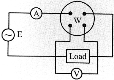 Therefore the power factor of given load = P/V x i
Class 12th physics Long Type question in English
| S.N | Physics Long Type Question English Medium |
| 1. | ELECTRIC CHARGES AND FIELDS |
| 2. | LECTROSTATIC POTENTIAL AND CAPACITANCE |
| 3. | CURRENT ELECTRICITY |
| 4. | MOVING CHARGES AND MAGNETISM |
| 5. | MAGNETISM AND MATTER |
| 6. | ELECTROMAGNETIC INDUCTION |
| 7. | ALTERNATING CURRENT |
| 8. | ELECTROMAGNETIC WAVES |
| 9. | RAY OPTICS AND OPTICAL INSTRUMENTS |
| 10. | WAVE OPTICS |
| 11. | DUAL NATURE OF MATTER AND RADIATION |
| 12. | ATOMS |
| 13. | NUCLEI |
| 14. | SEMI CONDUCTOR ELECTRONICS |
| 15. | COMMUNICATION SYSTEMS |