Q.1. State Kirchhoff’s rules. Obtain the condition for a balanced wheat stone bridge.
Ans ⇒ Kirchhoff’s rules first law : According to this rule algebraic sum of all currents meeting at a point in a circuit is always zero.
Let I1 and I2 currents are meet at 0 point and I3, I4 & I5 currents are but going from point 0, then We have, I1 + I2 – I3 – I4 – I5 = 0
In coming currents are taken positive and outgoing currents are taken negative. This lawd is based on the law of conservation of charge.
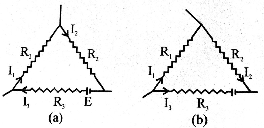
Second Law : According to this law the algebraic sum of product of current and resistance in each loop of a circuit is equal to total e.m.f. present in that loop.
If I1, I2 & I3 current are flowing through each loop and its corresponding resistance are R1 – R2 and R3 respectively, then we have
I1R1 + I2R2 – I3R3 = 0
and I1R1 + I2R2 – I3R3 + I2 r = E
Where r is internal resistance of cell and E is its e.m.f.
Balanced condition in wheatstone bridge : The most important applications of Kirchhoff’s applications are over wheatstone bridge by which electric resistances are compared. Circuit diagram has been shown in fig. Here P,Q,R, & X are four resistance which have been shown across four arms of parallelogram ABCD. A. galvanometer has been shown across the joint of P & Q and X & R. In external circuit there is a cell and a plug key. In fig. X is unkown resistance.
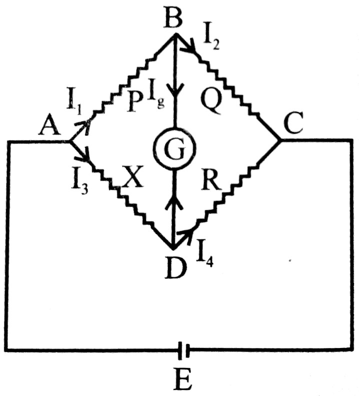
When circuit is switched on then current flows in circuit and deflection is observed in galvonometer. Now values of P, Q & R are so adjusted that deflection in galvanometer becomes zero. This is called balanced condition of Wheat-stone bridge.
Applying Kirchhoff’s first law (Point rule) at B.
I1 – I2 – I4 = 0
or, I1 – I2 = 0
or, I1 = I2 … (i)
Again applying same law on point D.
I3 + Iq – I4 = 0
or, I3 = 14 … (ii) (∵ Iq = 0)
Now applying loop rule in ABDA, I1P = I3X = 0
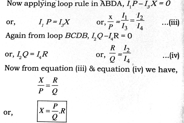
If value of P, Q & Rare known so X can be easily calculated.
Q.2. Explain the working principle of a potentiometer using a diagram. How will you compare emfs of two cells ?
Ans ⇒ Theory : The figure shows a schematic diagram of a potentiometer. A long resistive wire AB is connected at one end to accumulator (cell). The negative of the battery goes to the other end through Rh and key. Another cell ε’ whose emf is to be measured has its positive terminal connected to ‘A’ and negative terminal goes to through galvanometer. Jockey J can be adusted so that no current passes through G.
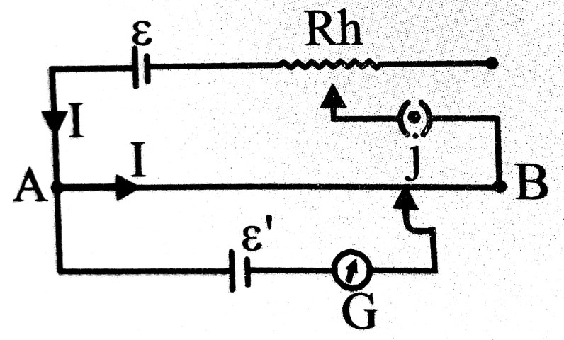
If an accumulator of contant emf ε allows current- I through AB, the potential drop between A and J is directly proportional to length AJ, and can be varied from 0 to ε by adjusting J. If r be the resistance per unit length them a length lof the wire will have a poential drop Ilr.
If I be adjusted for balancing ε’ in the circuit at a length l’,
cell of emf ε” ε’ = Il’r
For another length I” is obtained, where
![]()
Q.3. What are Joule’s laws of heating effect of current ? How are they experimentally verified ?
Ans ⇒ Joule’s laws of heating effect of current : When a current of strength I flows through a conductor of resistance R during time interval t, heat produced is given by
H = I2 Rt → In joule and H =![]() In calorie
In calorie
(a) First law : If R and t are kept constant then ![]()
(b) Second law : If I and t are constant then ![]()
(c) Third law : If I and R are constant then ![]()
Verification of Joule’ law : For verification of first law we take a single coil which is dipped in liquid in joule’s calorimeter and its ends are connected to T1 & T2 terminals.
If currents of strength I1 & I2 are allowed to flow through conductor for same time interval. If temp differences are θ1 & θ2 In two cases then we find that
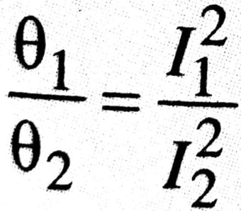
But before boiling,
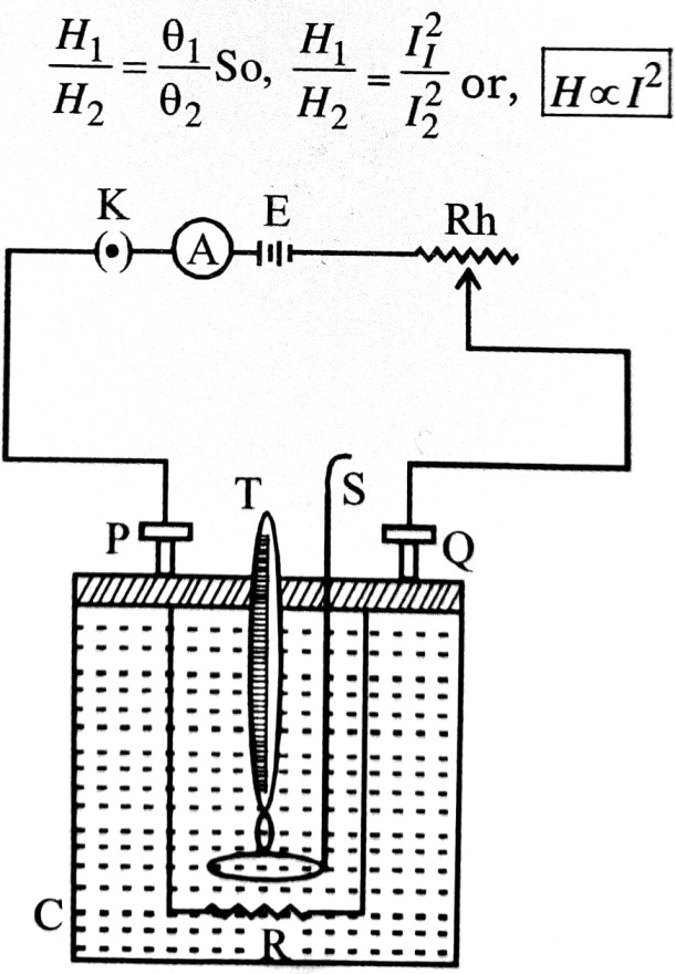
For verification of second law we take two coils of different resitance R1 & R2. They are connected in circuit one by one same current is allowed to flow through same time interval.
We find that ![]()
For verification of third law we take a single coil. It is connected in circuit and same current is allowed to flow for different time interval.

Q.4. State Ohm’s law and write how will you verify it.
Ans ⇒ Ohm’s law : At constant temperature and chemical composition, 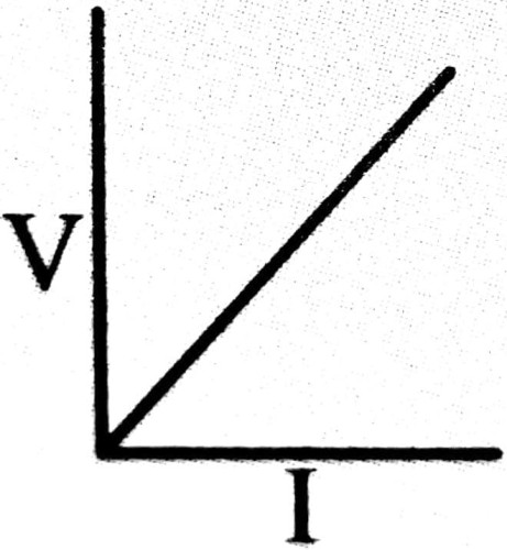 the current is directly proportional to the potential drop applied. If V be the applied potential difference and I be the current, them
V α I
⇒ V = (constant) x I
The constant is Which is called resistance of the conductor.
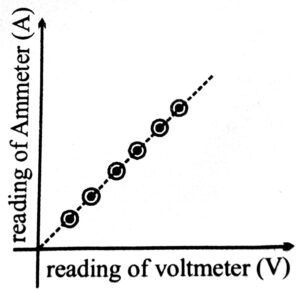
The conductors that obey Ohm’s law show its characteristic graph of a straight line passing through origin.
Verification : A potential divider circuit is used to apply variable potential drop across the conductor. The current is measured by ammeter A and voltmeter V measures applied voltage. Desired voltage can be obtained by changing position of jockey J.
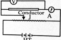
The graph between V and I is plotted. Its shape is straight line passing through origin. This verifies Ohm’s law.
Q. 5. What do you mean by drift velocity and mobility ? Discuss current density.
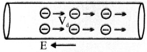
Ans ⇒ Drift Velocity : When a conducting wire or conductor is connected the terminal of cell then p.d. is set up, so an electric force acts on free electrons of conductor due to electric field. It accelerates them in direction opposite to field. These electrons colide with positive ions & neutral atoms again & again, so their speed do not increase due to electric force.
Obviously imposed potential difference provided a small constant velocity along the legth of conductor, This constant velocity is called drift velocity. Its value (≃10-2 cm/s ) is very small in comparison to rms speed (107cm/s). It is given by
![]() Where is current, n is the number of free electrons, A is the area of under for and charge on electron.
Where is current, n is the number of free electrons, A is the area of under for and charge on electron.
Mobility : It is driff velocity per unit field μ = ![]()
Mobility of electron ![]() Mobility of hole (+μh) = eτh/mh
Mobility of hole (+μh) = eτh/mh
Current density The amount of current passing through unit cross sectional area of a conductor is called current density. It is denoted by J. Therefore, j
= I/A → ampere / m2
Class 12th physics Long Type question in English
| S.N | Physics Long Type Question English Medium |
| 1. | ELECTRIC CHARGES AND FIELDS |
| 2. | LECTROSTATIC POTENTIAL AND CAPACITANCE |
| 3. | CURRENT ELECTRICITY |
| 4. | MOVING CHARGES AND MAGNETISM |
| 5. | MAGNETISM AND MATTER |
| 6. | ELECTROMAGNETIC INDUCTION |
| 7. | ALTERNATING CURRENT |
| 8. | ELECTROMAGNETIC WAVES |
| 9. | RAY OPTICS AND OPTICAL INSTRUMENTS |
| 10. | WAVE OPTICS |
| 11. | DUAL NATURE OF MATTER AND RADIATION |
| 12. | ATOMS |
| 13. | NUCLEI |
| 14. | SEMI CONDUCTOR ELECTRONICS |
| 15. | COMMUNICATION SYSTEMS |