10. WAVE OPTICS
Q.1. Derive an expression for angular fringe width in Young double-slit experiment.
Ans ⇒ Young’s double slit experiment : The required condition for interference that two source should be coherent. Young got success in obtaining interference fring, using source like this. There is a narrow slit infront of light source. There are two holes in a screen (S1 & S2) which works as secondary source. Situation has been shown in Fig.
The crests of waves are shown by dark lines & through are shown by dotted lines.

Since S1 & S2 are originated from same source so they are co-herent. When there is superposition of light waves energing by S1 & S2, interference frings are produced.
Those points where crest of one wave meets with crest of the other or through meets with through of the other then intensity of light is maximum and interference is constructive. But those points where crest of one wave meets with through of the other interference is destructive.
To exhibit phenomenon of interference Fresnel used biprism with the help of this prism two coherent sources can be obtained from a primary monochromatic light source. It is made with the help of two prisms whose refracting angles are very small (nearly 30′). Their bases are in contact with each other, so their one angle in nearly 1790.
When it is placed near a monochromatic light source, light appears to be coming from S1 & S2 i.e. S1 & S2 are virtual image which are coherent. So there is superposition of light waves coming out as a result interference frings are obrtianed on screen.
Determination of wavelength –
Situation has been shown in fig,.
Path diff. = S2P2 – S1P
From fig. (S1P)2 = D2 + (x – d)2 & (S2P)2 = D2 + (x + d)2

If OP is very small, then S1 P = S2 P = D so path diff ![]()
For constructive interference, path diff. = nλ
. ![]()
If distance of nth & (n + 1)th frings are xn & Xn+. then fringe width = xn+1 – xn
. ![]()
In β (fringe width) d & D are known, then D can be easily calculated.
Similarly in case of destructive interference can be obtained.
Expression for fringe width :
From (c) we get, for constructive interference ![]() & for destructive interference
& for destructive interference
![]() i.e. width of dark & bright both fring are same.
i.e. width of dark & bright both fring are same.
Here D-Distance of source from screen, λ – Wavelength of light waves.
2d-Distance between two coherent light sources.
Q.2. Explain Huygen’s Principal of wavelets and on the basis of the principle establish (a) reflection of light (b) refraction of light.
Ans ⇒ Huygens’ principal of secondary wavelets : It is a geometrical means by which the position of any wave front is found at any moment relative to a specific wavefront. According to this principle, every point of the primary wavefront acts as the secondary source of light for the production of waves. The small waves called wavelets produced by the secondary sources are called secondary wavelets.
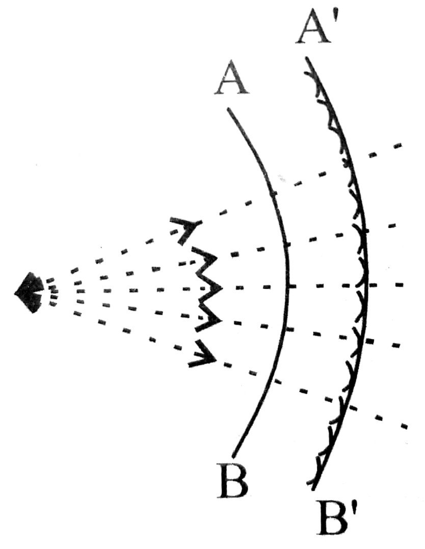
S is the source of light from which spherical waves propagate in all direction. AB is the position of the wavefront any time t. To know the position of wavefront after a small time Δt we take all the points on AB as the centre and CΔt as the radius and draw spheres. The common tangent at the spheres A’B’ is the position of the wavefront. In this way light propagets in the entire medium. Here C is the velocity of light.
(a) Reflection of light : ZZ’ is a reflecting surface shown in fig. A plane wavefront ALB is incident on the surface. OA is ⊥r to wave front. Secondary waves are produced after striking the incident wave front on surface and it moves with same speed in upward direction.

If its speed is v and wavefront takes time t on going from B to A then it is clear that at t = 0 it will strike at A. But point B will not strike at surface. If plane were absent then in time t wavefront reaches A’D. Here AD parallel to AB but in presence of ZZ when secondary waves start from A then

Beside it, the incident ray, reflected ray and normal at the point of incident are in same plane. It explains laws of reflection.
(b) Refraction of light : Let ABC be a plane wavefront incident on a plane at angle i, separating two media. The speed of light in two media are C1 and C2. If it is shown that wave coming fromt point B of incident wavefront, touches the imaginary surface EG after time t then this imaginary plane will be refracted wavefront.
The wavelet coming from B travels in first medium a distance BD and reaches the point D of refracting surface. If refrecting surface wave absent then it would reach point J at time interval t, with speed C. Now we draw ⊥r DF on EG from point D.
Δ AEG and Δ DEF are similar.
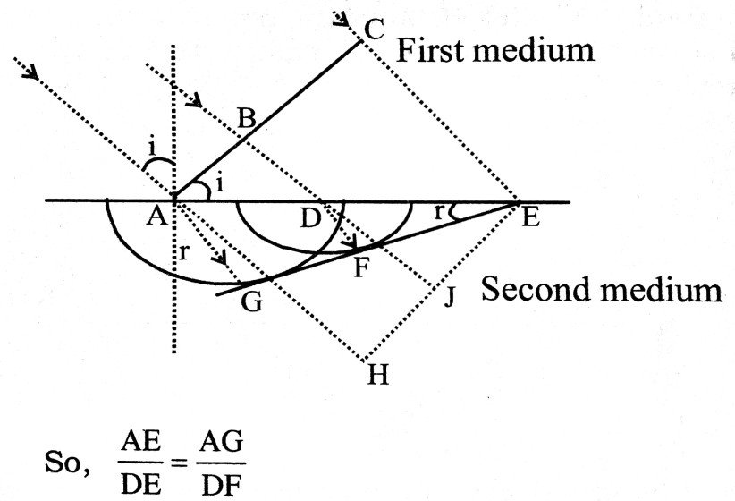
If refracting surface were not present then after time t the new place of AC is HE. But during this interval wavefront passes through AG not from AH.
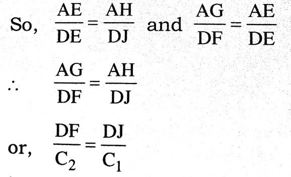
So, It AH = C1t and AG = C2t
Δ AHE and Δ DJE are similar.
. 
i.e., In second medium time taken by wavefront coming from D to F is equal to time taken by wavefront to J from D in absence of second medium. So in time ‘t’ wavefront coming from B reach D from in second medium and then reaches F from D in second medium. Besides it we known that DE ⊥’ EG. So, wavefront coming from B touches at F of imaginary plane EG at end of time t. So it shows that EG is refracted wavefront.
From geometry,

Incident wavefront, refracted wavefront and normal at the point of incident all lie in same plane.
So, phenomenon of refraction is explained by wave theory.
Q.3. What is Fresnel’s Biprism ? Describe an experiment to determine the wavelength of light by using a biprism.
Ans ⇒ Fresnel’s Biprism : It is made up of two acute angled prisms with their bases in contact, forming a single obtuşe angled prism. In actual practice the prism is ground from a single optically true plate. The acute angle a on both sides is of the order of 30′ or one degree. The prism is placed with its refracting edge parallel to the line joining the source and the point 0 on the screen placed perpendicular to the plane of paper.

In this way, line SO is perpendicular to the base of the prism.
Production of two coherent sources and interference fringes : When light from the source S falls on the lower portion of the prism, after refraction it appears to come from the virtual image B. Similarly light from the source S falling on the upper portion, after refraction appears to come from the virtual images A. Hence A and B act as two coherent sources. The distance x between the biprism and the source S is to adjusted that the virtual images A and B lie very close to each other. Interference fringes of equal width are produced between band con the screen placed at a large distance y from the biprism. To observe the fringes, screen is replaced by a micrometer eyepiece. If dis the distance between the two virtual sources A and B, D is the distance between the source and the screen and β is the fringe-width, then
![]()
if d, D and β are known, the wavelength of light can be determined
Experimental arrangement : Adjustment : A narrow adjustable slit S, biprism, and a micrometer eye-piece E are arranged in uprights on the bed of an optical bench in the same straight line and at the same height. The slit is made vertical and parallel to the edge of the biprism by rotating it in its own plane and is illuminated with monochromatic source of light the wavelength of which is to be determined. The biprism is moved parallel to the axis of the optical bench till on looking, through it along the axis of bench, two equally bright vertical sources A and B are seen. The eye-piece is moved at right angle to the length of the bench till the overlapping region is brought into field of view of the micrometer eye-piece. The slit is made narrow till the fringes appear in the focal plane F of the eye-piece. If the fringes are not clear, the biprism is rotated in its own plane till the edge of the biprism becomes exactly parallel to the slit and the fringes become very clear.
 (i) Determination of fringe wideth β : To determine fringe width β,
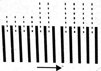 the fringes are first obtained in the field of view of the micrometer eye-pice.The vertical cross-wire is made to coincide with the centre of a particular bright fringe. Considering this as zero position, the position of the eye-piece is read on the scale. The micrometer screw is moved side-ways in the direction of the arrow-head and the number of fringe that pass across the cross wire is counted, as shown in fig. The position of the eye piece is again read on the scale, then
![]()
(ii) Determination of D : The distance D between the slit and the focal plane of the eye-piece is found out by noting their positions on the scale of the optical bench. This gives uncorrected distance. The correction to be applied is found out by adjusting a knitting needle between the slit and the eye-piece so that its one end touches the slit and the other end is clearly in focus when seen thought the micrometer eye-piece. The correction to be applied is found in the usual way.
(iii) To determine d : To determine dthe distance between the two virtual sources A and B, a convex lens whose focal length is less than one fourth of the distance between the slit and the eye piece i.e., D is mounted between the biprism and the eye-piece without disturbing their positions. The position of the lens is adjusted, as shown by complete lines till a sharp pair of the slits is obtained in the field of view of the eye-piece. The distance between these two images is measured. Let this be denoted by c1.
It u is the distance of slit and v that of eye-piece from the lens, then

The lens is now moved to the position shown by dotted lines till again a pair of images of the slit is seen in sharp focus. The distance between these two sharp images is again measured. Let this be C2, then

Determination of wavelength : As β, d and D are known, the wavelength λ can be determined, using the relation ![]()
Class 12th physics Long Type question in English
| S.N | Physics Long Type Question English Medium |
| 1. | ELECTRIC CHARGES AND FIELDS |
| 2. | LECTROSTATIC POTENTIAL AND CAPACITANCE |
| 3. | CURRENT ELECTRICITY |
| 4. | MOVING CHARGES AND MAGNETISM |
| 5. | MAGNETISM AND MATTER |
| 6. | ELECTROMAGNETIC INDUCTION |
| 7. | ALTERNATING CURRENT |
| 8. | ELECTROMAGNETIC WAVES |
| 9. | RAY OPTICS AND OPTICAL INSTRUMENTS |
| 10. | WAVE OPTICS |
| 11. | DUAL NATURE OF MATTER AND RADIATION |
| 12. | ATOMS |
| 13. | NUCLEI |
| 14. | SEMI CONDUCTOR ELECTRONICS |
| 15. | COMMUNICATION SYSTEMS |